Tool Path Tools
The tool path tools can be used to define exactly where the tool path falls during output.
For more information about tool paths, see Create Tool Path: Select one of the options to create a tool path. For full descriptions and explanations for configuration, if not populated below, see Tool Path Tools. .
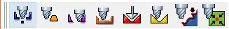
From left to right:
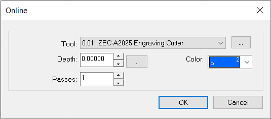
Online: Select for the tool path to follow the edge of a shape with a cut offset of zero.
The Online dialog appears. Select the tool, the maximum cutting depth, number of passes, and color layer to which the tool path is applied. If you click the ellipsis ( ) next to depth, the Engrave Parameters dialog appears (see below for details).
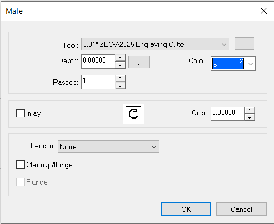
Male: Select for the tool path to fall to the outside of the shape, so the offset equals one-half of the bit width.
The Male dialog appears. Select the tool, the maximum cutting depth, the number of passes, and the color layer to which the tool path is applied. If you click the ellipsis () next to depth, the Engrave Parameters dialog appears (see below for details). Select Inlay if you have two pieces that must be flush, as it cuts rounded outer and inner corners. Set the inlay size in the Gap field.
To add a lead in (an additional portion added prior to the shape cut to prevent distortions), select Normal (short distance prior to shape cut so the tool is in the material prior to the edge), Ramp (combine the lead in with a sloped approach to the shape), or On Line Ramp (follow the expected cutting path as it initially lowers down into the material).
Note: When a lead in is specified, the Bridge function is disabled.
Select Cleanup/Flange to finish the job by tracing the edge of the object, resulting in a continuous smooth surface without "steps" from multiple depth passes.
Note: If you require a glue channel underneath an inlaid object, an additional depth pass can be set during clean up.
Select Flange (Cleanup/Flange must be enabled) to define how a "tab" or "shoulder" is applied to a piece being cut. A flange may be added to a male or female piece to prevent movement. Set the flange height.
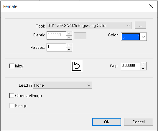
Female: Select for the tool path to fall to the inside of the shape, so the offset equals one-half of the bit width.
The Female dialog appears. For configuring controls, see above (Male) for tool path descriptions.
Fill: Select to define a series of cutting paths designed to remove material from inside of a selected shape.
The Fill dialog appears. For configuring controls, see above (Male) for tool path descriptions (many are duplicated).
Select Fine tool to remove any rough or leftover material from the initial fill pass. Choose the tool and depth.
Set a Fill style using the drop-down list (a preview shows the style). Set the fill overlap. Some settings allow for optimized spiral fill. Select to optimize fill passes.

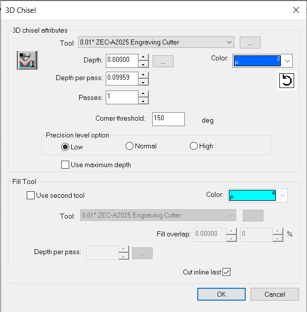
3D Chisel: Select to define a cutting process that varies the depth of a contour tool along the defined path.
The 3D Chisel dialog appears. For configuring controls, see above (Male) for tool path descriptions (many are duplicated).
The Calculate Minimum Depth button ( ) automatically calculates the minimum depth required to form a pointed object (based on the type of tool used and the selected object).
Click the Direction button ( ) to change the direction of the tool path.
Set the corner threshold and precision level.
Use the Fill Tool section to enable a second tool to complete fill operations. Select the color of the path, the tool, the depth per pass, and specify if you want to cut inline last.
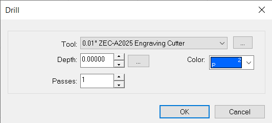
Drill: Select to place drill points on the workspace.
The Drill dialog appears. Select the tool, the maximum cutting depth, the number of passes, and color layer to which the tool path is applied. If you click the ellipsis () next to depth, the Engrave Parameters dialog appears (see below for details).
Click the workspace to place a drill point. Once the drill points are placed, use the close button in the SmartBar ( ) to exit the Drill state. Alternatively, the Space Bar or clicking Select Tools can also be used.
To update the depth, select the tool path, and navigate to Edit > Edit Toolpath. The Engrave Parameters dialogue will appear on screen. Adjust the depth as needed.
Drill Contour: Select to place drill points along the contour of selected objects.
The Drill dialog appears. Select the tool, the maximum cutting depth, the number of passes, and color layer to which the tool path is applied. If you click the ellipsis () next to depth, the Engrave Parameters dialog appears (see below for details).
The Fit Drill Points to Contour dialog appears. Select the number of points that will be evenly spaced, the distance between the points, and the offset from the start of drill point placement. Select Nodes to place drill points according to each node, or Nodes and Distance to place drill points according to each node of the object, with additional points placed according to distance.
Drill Center: Select to place a drill point in the center of the selected object.
The Drill dialog appears. Select the tool, the maximum cutting depth, the number of passes, and color layer to which the tool path is applied. If you click the ellipsis () next to depth, the Engrave Parameters dialog appears (see below for details).
Engrave Parameters Dialog
|
Use the table to configure tool options |
|
|---|---|
| Depth | Set the desired depth. |
| Depth per pass | Set the desired depth per pass. |
| Last pass depth | Set the last pass depth. |
| Passes | Set the number of passes (the depth per pass is calculated). |
Fiery family of software products
Making your machines run better
Copyright © 2025, Fiery LLC. All rights reserved. Privacy Policy.