Tool Path Tools
The tool path tools can be used to define exactly where the tool path falls during output.
Note: If you have already configured a tool path using the [selected tool path] Default dialog, the dialog will not appear again unless you go to Machine > Create Tool Path > [select tool path].
When you go from Tool Path Tools > [select tool path] or Machine > Apply Tool Path > [select tool path], the tool path presets are used and the tool path is automatically applied.
If you want to apply a configured tool path, use Tool Path Tools or Machine > Apply Tool Path > [select tool path]. If you want to configure the tool path and apply it, use Machine > Create Tool Path > [select tool path].
If you are using a tool path for the first time and the Default dialog appears, to configure, see Default dialog.
Per maggiori informazioni sulle impostazioni, vedere Create Tool Path: Select one of the options to create a tool path. For full descriptions and explanations for configuration, if not populated below, see Tool Path Tools..

Da sinistra a destra:
Online: Select for the tool path to follow the edge of a shape with a cut offset of zero.
Male: Select for the tool path to fall to the outside of the shape, so the offset equals one-half of the bit width.
Female: Select for the tool path to fall to the inside of the shape, so the offset equals one-half of the bit width.
: Select to define a series of cutting paths designed to remove material from inside of a selected shape.
3D Chisel: Select to define a cutting process that varies the depth of a contour tool along the defined path.
Bevel: Select to define a three-dimensional cutting process that produces a bevel appearance.
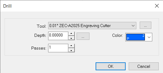
Drill: Select to place drill points on the workspace.
Click the workspace to place a drill point. Once the drill points are placed, use the close button in the SmartBar ( ) to exit the Drill state. Alternatively, the Space Bar or clicking Select Tools can also be used.
To update the depth, select the tool path, and navigate to Edit > Edit Toolpath. The Engrave Parameters dialogue will appear on screen. Adjust the depth as needed.
Drill Matrix: Select to place a series of drill points across an object.
The Drill Array Options dialog appears. Select an array, the number of copies, and the drill placement.
Drill Contour: Select to place drill points along the contour of selected objects.
The Fit Drill Points to Contour dialog appears. Select the number of points that will be evenly spaced, the distance between the points, and the offset from the start of drill point placement. Select Nodes to place drill points according to each node, or Nodes and Distance to place drill points according to each node of the object, with additional points placed according to distance.
Drill Center: Select to place a drill point in the center of the selected object.
The Default dialog appears. In the Template tab, select the material and the template. In the Basic Cut tab, set the control, tool, depth, surface, and total passes. Select for a fixed first pass and last pass, and set the maximum per pass. Set the feed and plunge rates, spindle speed, and dwell time.
Drill Corner: Select to place drill points in the corners.
The Drill Corners dialog appears. Set the bounds offset for X and Y and select whether to place extra drill points with horizontal and vertical copies.
Drill Braille: Select to apply drill points to any text that has been converted to "brpunch.vef" font.
Drill Braille can also be applied to the center of selected objects.
Fiery family of software products
Making your machines run better
Copyright © 2026, Fiery LLC. Tutti i diritti riservati. Informativa sulla protezione dei dati personali.