Graphics Edit Tools
The graphics edit tools can be used to edit objects. To see editing tools, right-click in the workspace (for more information, see Node palette).
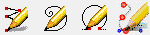

From left to right:
Node edit: This tool is used for creating and editing polygons. Select to edit nodes. Click a node to select that node. Hold down Shift and click to add nodes to the selection.

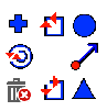
From left to right:
- X, Y coordinates
- Absolute mode: New nodes are placed with respect to the
- Relative mode: New nodes are placed with respect to the previously created node.
- Polar: For placing nodes, the edit fields represent the angle and length of the new node position.
- X, Y coordinates: For placing nodes, the edit fields represent X and Y of the new node position.
- Arc, node, segment edit: See Node palette.
Free edit: Select to trace a polygon object by hand. Click and drag to draw. Release to create. If the start and end are close, a closed contour will form, otherwise go to Arrange > Close Graphics. To control line thickness, click the thickness button ( ) and set the line thickness.

From left to right:
- Enable element spacing and disable line thickness.
- Enable line thickness: Apply line thickness when drawing and disable element spacing.
- Select color: Select line color.
- Center to center spacing: Select to space elements from center point to center point.
- Edge to edge spacing: Select to space elements from edge to edge.
- Enter a value: Enter a value for element spacing.
- Select elements: Open the Element Selector dialog to add elements.
Arc edit: Select to create new nodes for an object.

From left to right:
- X, Y coordinates
- Absolute: New nodes are placed with respect to the
- Relative: New nodes are placed with respect to the previously created node.
- Polar: For placing nodes, the edit fields represent the angle and length of the new node position.
- X, Y Coordinates: For placing nodes, the edit fields represent X and Y of the new node position.
- Arc bulge mode: The third edit field represents the bulge of the curved line segment.
- Arc radius mode: The third edit field represents the radius of an imaginary circle. The new line segment is drawn along the circumference of the imaginary circle and connects the points that would have formed a straight line.
- Arc, node, segment edit: See Node palette.
Bézier node edit: Select to create and edit Béziers (vectors composed of nodes and curves). Click to place a node, or click and drag to place a node and define the curve.

From left to right:
- Line: Forms straight lines between nodes.
- Cusp: Allows for handles and curves to be adjusted independently.
- Smooth: Allows for handles to be adjusted independently.
- Symmetrical: Handles and curves are linked.
- Break: Remove a connecting line segment between nodes.
- Join: Join two selected nodes with a connecting line segment.
- Connect: Join two selected nodes with a connecting node at their midpoint.
- Add node: On an existing curve, click to place an additional node.
- Delete node: Delete nodes by clicking or selecting.
- Scale: Inserts bounding box for moving and scaling selected nodes.
- Rotate: Inserts bounding box for rotating the selected nodes.
- Node edit
- Segment edit
- Relative position
- Absolute position
- Coordinates: Set the x and y coordinates for the selected node.
Node palette
When editing objects, by holding down the right mouse key, you can access the node palette (choices depend on mode) to choose a function.
Tools:
- Arc Edit: Used to create new nodes and alter existing ones.
- Node Edit: Used to edit existing nodes.
- Segment Edit: Used to edit a segment between two selected points. Clicking on the selected segment places a node.
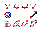
From top left, clockwise:
- Sharp corner: Change to corner node or create new corner nodes.
- Join: Join selected nodes or join the endpoints of a selected contour.
- Curve point: Change to curve node or create new curve nodes.
- Set start point: Set the start point where output begins on the contour.
- Tangent node: Change to tangent node or create new tangent nodes.
- Break: Break the contour at the selected node.
- Delete point: Delete the selected nodes.
- Toggle direction: Toggle direction of selected contour between clockwise and counter-clockwise.
From top left, clockwise:
- Make cusp: Allows for handles and curves to be adjusted independently.
- Make smooth: Allows for handles to be adjusted independently.
- Make symmetrical: Handles and curves are linked.
- Make line: Forms straight lines between nodes.
- Set start point: Set the start point where output begins on the contour.
- Connect: Join two selected nodes with a connecting node at their midpoint.
- Join: Join two selected nodes with a connecting line segment.
- Break: Remove a connecting line segment between nodes.
- Delete: Delete nodes by clicking or selecting.
- Toggle direction: Toggle direction of selected contour between clockwise and counter-clockwise.
Fiery family of software products
Making your machines run better
Copyright © 2026, Fiery LLC. All rights reserved. Privacy Policy.